802Projects
I decided to document this in case anyone else is dealing with it. I had an original T56 Magnum setup from Grannas Racing (not the magnum F). This means I originally had his v1 tunnel cover. I switched over to his T56 Magnum F setup because I was not a fan of the Sikky setup. This means I had to swap to his 2 tunnel cover. This was no big deal as the cutout for the v2 setup was slightly bigger than the v1 setup.
I had issues with his template. I think he marked the "this side up" on the wrong side, or he had the front slanted line angled the wrong way. If your template was fine, you can thank me for being the guinea pig as Joel said he'd look into it. Here I'm showing the paper template the "wrong" way based on his "this side up". Notice how the front slant matches?
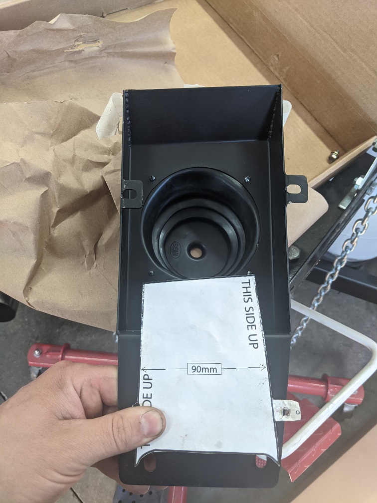
This shows it the "right" way based on the "this side up". Notice how the front slant goes the other way?
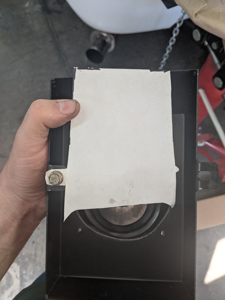
Unfortunately I didn't notice this until I cut out the template:/ It lead me to having the slant going the opposite way. I had to fix this by welding a front lip onto the tunnel cover. In the end this wasn't a bad thing as it gave more surface area for the seam sealer to adhere to. Rest assured I scuffed up everything and painted the modified v2 cover before installing it.


Now this is what I hated about the tunnel covers he sold. He used a "Mr Gasket 1651" boot. This is probably the cheapest boot you can find online. It's also an angled boot which isn't ideal for a shifter that sticks straight up. To top it off, the boot didn't seem very centered around the shifter. Here it is in neutral. Notice how it is already pushing the boot backwards?

Here it is in 3rd. There is no tension on the boot here.

Then here it is shifted back into 4th. It stretches the hell out of the boot.
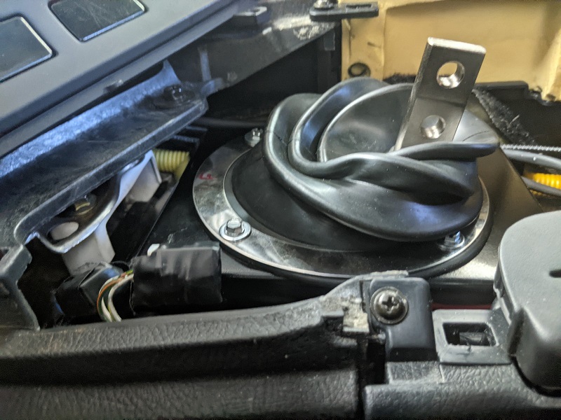
The collar on the boot was also very thin. The corners of the shifter arm are kind of sharp. That combination lead to the boot tearing easily. When I put the T56 Magnum F in, the boot on my v1 cover was already torn. It had less than 1000 miles on it. I even managed to tear the boot that came on the v2 cover sliding it on. I had to buy another "Mr Gasket 1651" kit. I took a file to the corners of the shifter arm to help with the sharpness. I also wrapped it in some electrical tape. I can tell you that it didn't help. When I inspected it last week, it was torn.
So I saw that Grannas now sells a new square boot setup. I believe it is a copy of the OEM boot meant for factory 6 speed Supras. He now has a v3 cover which looks like the v2 cover, just with the newer factory style boot setup. I emailed Joel to ask if it would be possible to install the new boot setup on the v3 cover. He confirmed it would work. He said for a while he was selling v2.5 setups which were exactly that. The v3 cover I think is the same as the v2 cover, only a little shorter in the front so you don't have to cut out as much. So I purchased it.
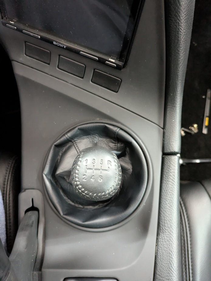
It still doesn't seem right. I don't know if Joel was mistaken, or if all his v3 kits have centering issues. Here is the car in neutral with the boot slid on. Notice the front of it does not cover the Mr Gasket boot hole. Maybe the hole sizes on the v3 kits are different? Also notice the back holes in the boot. They are right where the v2 cover drops down. You can't exactly put a bolt there. Maybe the v3 kits drop off a little further back? You could argue that maybe my setup is different. Maybe my transmission sits back further or something... But it doesn't. My car is a clean title with no accidents. I'm running factory subframe and factory motor mounts. My T56 Magnum F is bolted to the Quicktime bell housing Grannas sells which bolts directly to the motor. There is a metal ring that comes with the Quicktime housing I didn't use (as Joel says not to). If I had used that, it would have only put the transmission further back. Then finally if you look at the last picture on this page, you'll see the shifter arm comes up dead center of the console trim piece.

To me it seems like either...
1) the v2 transmission covers are not identical to the v3 transmission covers. Perhaps I have an early edition of the v2 cover. Or...
2) the v3 setups come with the boot bolted on them and they are installed a little farther ahead then they should be. Meaning when you slide them on, the shifter lever is pushing back on the boot some like Mr Gasket picture above when it is in neutral.
I didn't want to have tension on the boot. I wanted it to be perfectly centered in neutral. I also didn't want to have a gap in front of the boot. So here is what I ended up doing. I made a sandwhich plate for it.
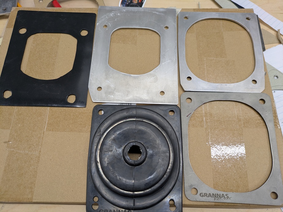
I started with the shifter in neutral and with the boot slid on. I marked the front holes. I installed rivnuts there. I couldn't install rivnuts for the rear holes as they were too close to where the v2 cover drops down. I had to move the rear holes forward slightly. This means I'd have to make new rear holes in the boot and the top cover.
Then I made a plate out of 1/8" thick aluminum that lined up with the 4 holes and had the perfect size opening for the shifter assembly. I made sure I can shift it through every gear without it hitting the plate. The front of the opening is also further back which means the boot will cover everything now and have support from underneath.
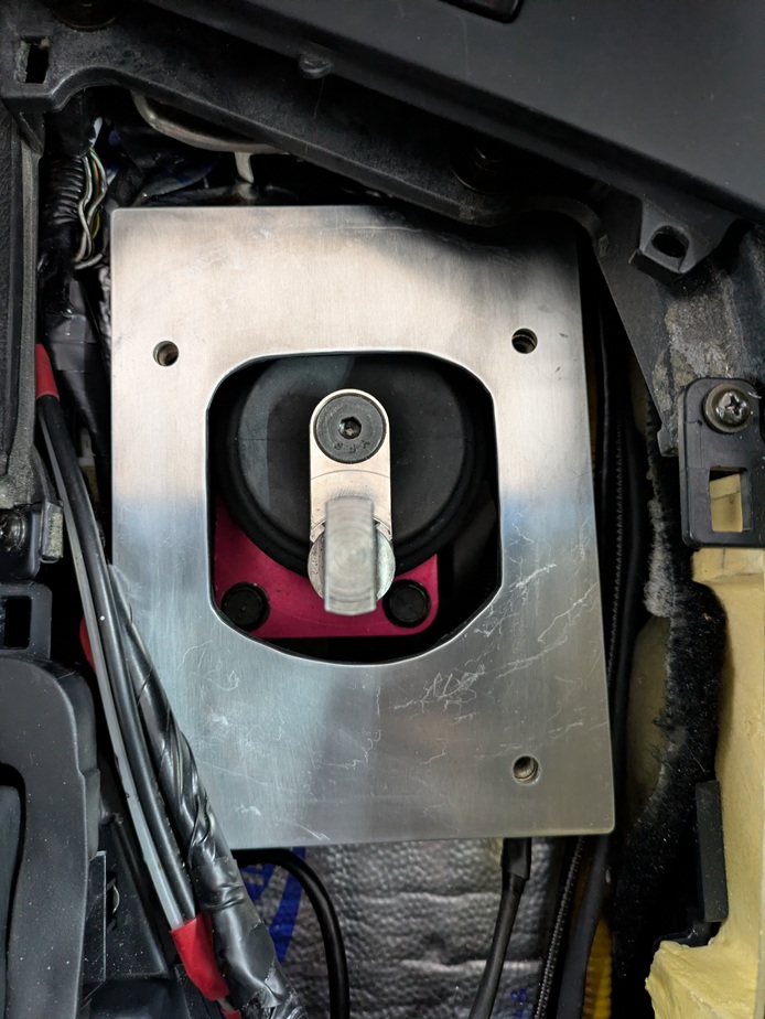
I intended to use seam sealer and glue the bottom plate down, but I opted to use some 1/16" high heat silicone mat instead as a gasket. This way it's removable. The rivnuts stick up a little so I cut bigger holes in the mat. This should give a me a nice flat fit.
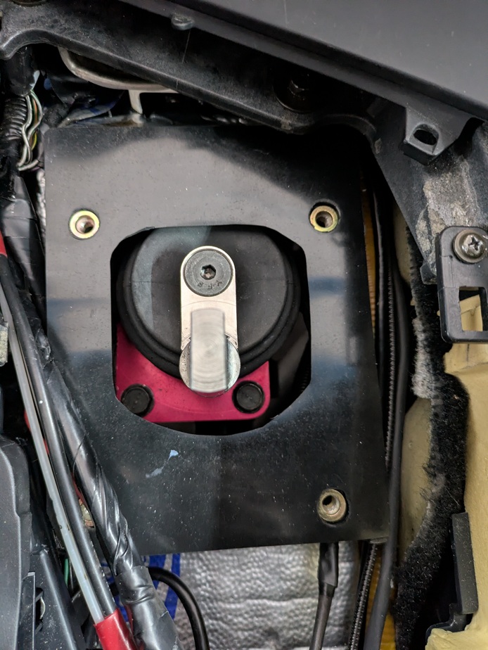
Next comes the boot. Notice the new rear holes I had to make.
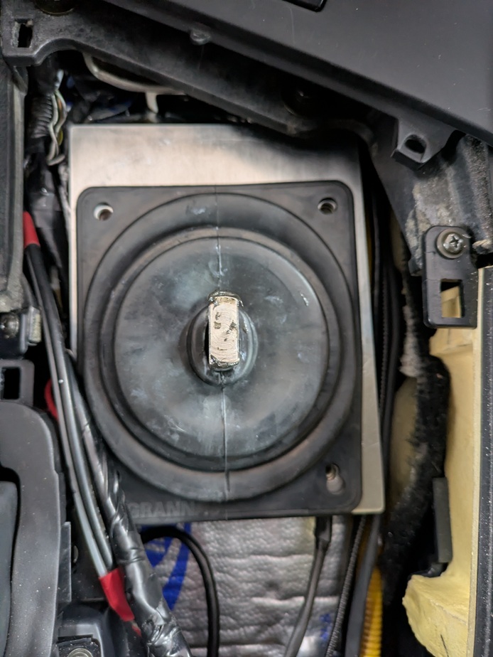
Then comes the shifter ring. I opted to make my own out of aluminum vs drilling new holes in the Grannas ring.

This seems to work well. It's entirely sealed. It's perfectly centered. It's removable. There are no gaps around the boot and it's got plenty of surface area squeezing it all around. In the pictures I don't have the boot pushed down all the way around the neck of the shifter lever. It goes from a round shaft to a square shaft. It is possible to push the rubber hole down so it surrounds the round part of the shaft. That is what I did, I just didn't take a new picture.
Then finally here is the end result with everything installed.